Linear electric encoders are linear members of the new electrical position sensing technology, including angular displacement encoders.
The linear encoder includes a scale and an interactive reading head. The scale bar is a printed circuit strip printed by a transmitter in the periodic style field. The reading head is also a conductive receiver style printed circuit substrate. A typical reading head has a shape of 6mm, which includes processing electrons and providing two outputs as a substitute for the measured sine function.
The interaction area between the reading head and the scale is usually between 25mm and 60mm, which will affect the average cycle of multiple conveyors. Overall, it provides a high signal-to-noise ratio, tolerance for mechanical installation errors, and overall sensitivity to certain pollutants.
Linear electric encoders differ from optical linear encoders in sine/cosine in the following aspects:
The scale is electrically driven,
Stimulated by simulated current,
The cycle is usually two sequential stages of importance,
The output is absolute,
The products of linear electric encoders have a very low DC branch, low harmonic distortion, perfect amplitude matching, and stability at high temperatures, which can be digitized (tampered with) to provide 10 micron sub micron resolution and accuracy or better.
Linear electric encoders exhibit multiple advantages over a long period of time, such as not being a radeoff between speed and resolution, outputting low-frequency signals, less prone to parasitic phase transitions, and PWM noise.
1. Principles of linear electric encoder
The electrical field of multiple metal plates between parallel plate containers is well-known for separating plates that are almost uniform in size compared to the minimum size of the plates. The variation range of parallel plate containers includes two insulating layers on each other, which are imitated together with conductive layers (equivalent to a small separation of fixed-size plates). A more short-lived base layer can move along a higher layer to provide load-bearing capacity. This is the basis for detecting the position of Class 1 electrical components, described below as one of the six possible shapes.
A Class 1 incremental linear encoder includes a fixed scale as shown in Figure 1 and a moving reading head. A repeating pattern of rectangular bars is printed on a scale bar (shown in A), where four consecutive vertical bars form a period of space. The individual vertical bars in each period are active under the action of simulated current and are moved by 90 degrees so that the waveform of even vertical bars is active between 0 degrees and 180 degrees, and odd vertical bars are active between 90 degrees and 270 degrees, quadrature wave.
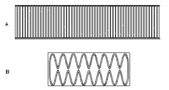
Figure 1 Incremental Class 1 linear encoder
The reading head receiver board (shown in Figure B) includes a sine wave mode on a scale equal to four companions, surrounded by a supplementary mode for a period of time. The gap separates the sine wave and supplementary mode as small as in reality, while the separation between the scale bar and the reading head is usually a single vertical bar in width.
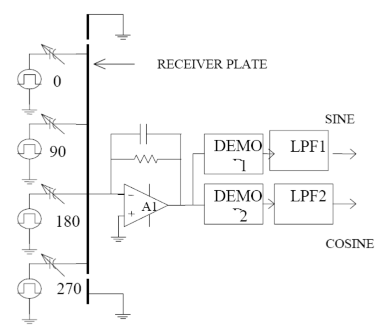
Figure 2 Signal processing of linear electric encoder
The synchronous detector is a basic analog multiplier that multiplies the output of the cost amplifier with a square wave, which is an active waveform between 0 degrees and 270 degrees, respectively. The result of net profit is the substitution and scale of two low-pass filters that output a reading head proportional to sine and cosine waves. The early position is combined with the instantaneous value of the sine and cosine signals translated into the incremental position of the reading head.
In mathematical language, if the function h (x) represents the sine wave generated by the reading head, the signal is output, and the overlap between them and their respective activity ranges are proportional to the coverage, which is matched as follows:
∫h(x)s1(x)dx and ∫h(x)s2(x)dx
S1 (x) and s2 (x) represent the quadrature within their respective stages.
Therefore, as a reading head travel, the output voltage image is a cross-shaped functional image associated with the reading head and scale function.
2. Absolute output linear electric encoder
In addition to the previously described good modes, linear encoders can adapt to providing an absolute output by providing a crude mode. The journey of reading in a good mode includes many periods; The output signal in the crude mode is proportional to the sine and cosine of the reading head position, but the length of the period is equal to the travel time of the entire reading head. Although the scale of absolute mode can be switched between two modes, the crude mode is only used when the power is turned on, marking the position of the reading head for a good period of time. The combination of good and rough mode reading provides early resolution and accuracy of good length and fidelity determination for the absolute position of the reading head, as well as the quantitative depth of processing electronic products.
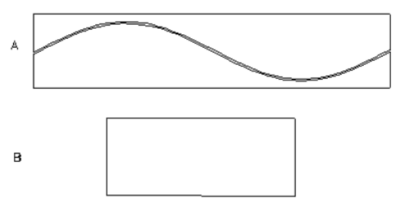
Figure 3 Rough concept pattern absolute linear encoder
Like good modes, the output signal of rough mode is also a product of cross correlation between a sine wave and square wave modes; However, the role of reading head and scale is opposite. Figure 3 illustrates a concept of scale and reading head in crude mode. The scale includes conductive bars that are split along their length according to the sine wave difference. The two parts of the scale move with opposite alternating voltages, while the reading head includes a square conductive plate associated with the amplitude of the change, as before. The signal generated by the reading head will be a sine wave for a period equal to the length of the scale, but due to the uncertainty of the sine function and the possibility of its amplitude being affected by tolerance for differences, a supplementary cosine signal is needed.
Figure 4 illustrates the multiple concepts of providing both sine and cosine functions of rough patterns at the same scale. The vertical bar is divided into two parts – the gap between even-numbered vertical bars is adjusted with the position of a sine function, while odd-numbered vertical bars are adjusted with the position of a cosine function. The sine and cosine vertical bars operate at the same frequency, but the quadrature relationship remains the same as before. In crude mode, the upper and lower parts utilize waveform activities with opposite stages. Like before, the hybrid output of the variable amplifier is separated into two parts by two synchronous modems, which can achieve correlation.
In the singularization relationship of the signal, there are two low-pass filters behind these two modems.
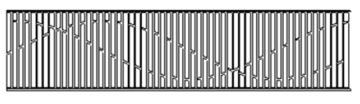
Figure 4 Rough/good linear encoder
In Figure 1, in order to reduce the impact of uniform spatial distance changes in the output signal on a good channel, the reading head mode is optimized. Such changes may cause the reading head to move along an imperfect mechanical guide. When moving up and down in symmetric mode, the first cancellation is fixed. Similarly, by ensuring correct symmetry on the left side of the pattern, the insensitive impact of the output is tilted on the coordinate axis.
Tilting the receiver board of the rough mode square wave receiver (Figure 3B) around the axis parallel to the travel axis will affect the balance of the upper and lower parts of the transmitter; Correspondingly, it affects the balance of sine and cosine outputs. To minimize this impact, the strategy shown in Figure 5 was used, where the vertical bars of the sine and cosine conveyors were reflected and related to the centerline, so two consecutive vertical bars were used as compensation.

Figure 5 A linear encoder style biased toward compensation
3. A period of time and its implications
During a period of time, an optical system is not suitable for accurately generating repetitive patterns. This is because the accuracy of the generated sine wave pattern is limited at least according to the non-linear grayscale level of the image medium. In principle, the bi-level of generating sine waves and the modulation approximation of pulse width can avoid this limitation, but the imaging mode will become a heavy burden related to elucidating and responding to uniformity. Different constraints will limit the length of the period of the sine wave pattern generated by diffraction.
The electrostatic domain is constrained by different rules and can be virtually generated in any cycle. In a parallel plate capacitor, the electrical field is unified. In addition to the Edge device that becomes its edge, the Edge device becomes smaller because the ratio to the size of the plate decreases. Therefore, a parallel plate capacitor may not include components that become smaller than separate boards, and the mode in the electrical field is limited in length rather than simply shortening the cycle.
A diffractive optical encoder will provide a sine wave, which theoretically could be infinitely inserted. However, in practice, the following drawbacks limit the insertion depth:
DC offset,
Mismatch of amplitude,
Overtone of alloys,
This indicates that the output of sine and cosine waves may result in an error that repeats once per cycle (electrical cycle), however, amplitude mismatch will result in an error that repeats twice per cycle. However, due to these errors, harmonic distortion can be compensated to some extent, and the sine cosine signal flow is generated in two separate photodiodes and thermometers, which may be maintained within a limited temperature range. On the other hand, due to the short period of operation of the optical encoder, it still provides important accuracy and resolution, and the above incompleteness is indicated as only a sub-partition error.
Electric linear encoders are different from optical encoders in some aspects, the biggest difference being the length of the period, which is, orders of magnitudes long (fes millers versus fes micrometers) To achieve resolution comparable to that of optical encoders much higher interpolation factor (quantization depth) is needed, and the sinusoidal outputs of the electric encoder must be significantly more accurate. Fortunately, the factors involved make that possible, as follows:
The quality of transmitting and receiving boards depends on an inherently accurate photographic production process,
The edge effect plays a positive role by reducing harmonic distortion – in the space of high attenuation in the sine wave domain.
The size of the interactive area between the reading head and the scale is flexible. The length of the reading head can be maximized, depending on the application, by dividing many cycles equally and improving accuracy.
Before demodulation, the output signal is simulated and shares a common receiving board and processing channel, so they are closer to ideal in terms of DC bias, amplitude matching, harmonic distortion, and signal-to-noise ratio, and are also stable at a certain temperature.
Long-term practical guidance and related low signal frequencies are:
There is no need to index the position, and even since there is a mechanical stop with good adaptability, the controlled travel in the incremental version is sufficient to identify the termination period that may be determined from its absolute position,
Reduce dynamic errors and parasitic phase changes,
Reduce the sampling rate when there are no errors in the high-speed loop,
Reduce adjacent sensitive PWM interference and occupy a separate spectral region,
Basically, there is no conflict between the highway and the resolution – as shown below
Accuracy requires increasing the response time of a good channel on a scale from a rough channel, that is, when the scale becomes longer, the response time of a good channel becomes shorter. To reduce this requirement, the changes schematically shown in Figure 6 will be minimized, with several coarse pattern cycles along the length of the scale. To avoid uncertain reading, their amplitudes are linearly modulated and positions that depend on the number of sine cosine rough patterns are calculated and used to identify the cycles of rough patterns. However, the importance of vectors also depends on the difference between the reading head and the scale – which can lead to serious errors. This error is compensated based on the fact that the importance of a good channel vector is sustained throughout the entire operation period for a specific gap. Therefore, in order to correct the signal in rough mode, it can serve for measuring the gap.
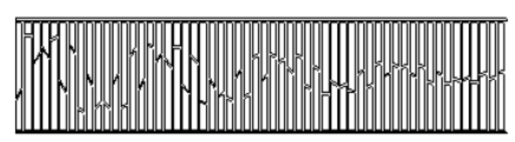
Figure 6 Amplitude modulation of rough mode
4. Signal-to-noise ratio
The noise model of the linear electric encoder is shown in Figure 7, where Cf=10pF is the feedback capacitance of the cost amplifier, Cs is the receiving board capacitance, and Cp is its parasitic capacitance to the grounded layer behind it. On a 25x60mm reading head, the channel receiving board with good sine wave is 7cm2. The optimized distance between the receiver and transmitter board lasts for 4 millimeters, during which it will be treated as 1 millimeter according to the length of the period, resulting in C=5pF. The concealed board is an internal layer in a printed circuit board, with an insulation constant of 4.5 and a distance of 0.5 millimeters usually separating the glass epoxy resin, resulting in Cp=45pF.
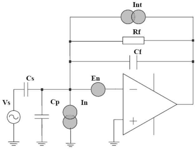
Figure 7 The Noise Model of Linear Electric Encoder
The main source of noise is in the early stages of the cost amplifier. The voltage acquisition of an ideal cost amplifier is – C/Cf -, derived from the ratio of capacitance to feedback capacitance, assuming infinite feedback resistance. In practice, a 10M Ω resistor is used and its effective value is increased by providing its output voltage (not shown) through a resistor voltage divider, making its impact negligible in frequency response.
The total amplifier output voltage noise density can be obtained at [2], [3]
4kT/Rf (in Figure 7) is the Johnson noise of the feedback resistor, where k=1.38×10⁻²³ and T=300o. The total value for Rf=10MO is 1.6×10⁻²⁷ [A2/Hz]. In 2, there is a FET input stage that typically has an order of 10-28 [A2/Hz], which is negligible in comparison with thermal noise – operating at a frequency of 10kHz will result in an output noise density of 4×10-15 [V2/Hz].
For an amplifier and upper capacitor with a voltage noise source of en=10nV/√ Hz, the noise density of the second noise source will be 3.6×10⁻¹⁵ [V2/Hz]. It is desired that the total output noise density of 10kHz is 8×10-15 [V2/Hz]
If the cutoff frequency of the low-pass filter in Figure 2 (which is also the bandwidth of the encoder output signal) is f0, the amplitude modulation signal output by the cost amplifier will occupy a frequency range of fc ± f0. Random noise within the frequency range of 2f0 will transition to baseband under synchronous demodulation, and the sensor’s limiting resolution will be set. The noise bandwidth for f0=1kHz will be 2kHz, and the RMS noise output before the amplifier will be 4 μ V.
If the carrier wave is a square wave, we should also add noise contribution at the interval between the third and fifth harmonic frequencies around us. However, due to the reduction and lower contribution of thermal noise, the added noise in the respective (1/3 and 1/5, based on Fourier coefficients) synchronous demodulator benefits is negligible
The output signal voltage of the cost amplifier is Vs Cs/Cf, and for peak to peak excitation voltage Vs=5V, it will be 2.5V. The maximum (full wave correction) signal value of the modem will be 1.25V, and its noise ratio to RMS will be 3×10⁵,
As is well known, Gaussian random noise will exceed 3.3 times its RMS value, and the RMS time is only 0.1%. In fact, it can never exceed 4 times its RMS value. The same applies to dynamic random signals, which are safely treated as 3/4 x10-57×104, which equals 16 bits.
4. Electrical interface, signal processing, resolution, speed
The linear encoder has a current consumption of 5mA and a primary DC supply of+5V for operation. This unusual low current value is caused by the load of low scale capacitors, low excitation frequency (10kHz), and CMOS processing circuits.
The output signals of sine and cosine are usually 2V peak to peak, and each provision will be different, while other common mode noise is reduced to a complementary pair. After the difference signals are digitized, they are converted into digital signals. The conversion algorithm depends on a tangent lookup table. This is based on the fact that all sine waveforms contain 8 reflections and/or repeated transformations of the same pattern. This can be displayed in the binary angle representation as an additional 3 bits (the first bit represents 180o) output calculated angle. An n-bit A/D converter provides n-2 utility bits (excluding flag bits and LSB). I want to output the resolution of binary angles, so it is n+1 bits. All conversion algorithms can be built on [4].
According to the above, a scale of 4 millimeters per cycle is combined with a 12 bit A/D converter, which will provide 4/213mm or 0.5 μ M resolution, however, a 14 bit A/D converter will provide 0.1 μ Resolution of m.
The maximum reading head speed of a filter with a cutoff frequency of 1kHz and a pitch of 4mm is 4m/Sec – independent of the specified resolution. As is well known, increasing the activity of the voltage will increase the signal-to-noise ratio and allow for increasing protocols, while enhancing the excitation frequency and filter cutoff frequency will allow for virtually infinite speeds.
5. Construction and accuracy
The scale and bottom layer of the reading head are manufactured using standard printed circuit technology. The thickness of the scale varies between 0.2 millimeters and 0.5 millimeters, while early good standard pitches were 1, 24, or 8 millimeters. The standard scale width is also 25 millimeters or 10 millimeters. The corresponding reading head – including all processing electrons with a length of 6 millimeters, is a segment of 60 millimeters and 40 millimeters, respectively.
The current technology allows for a minimum annoying early length of approximately 0.5 millimeters and the accuracy of manufactured models using new laser direct imaging (LDI) technology in some micron orders. However, the overall accuracy of the encoder is influenced by several other factors:
The average of many cycles,
Weakening of higher harmonics in the mode creates on-site embellishments,
The degree of mechanical changes in printed circuits closely follows the depiction of copper plates.
The accuracy of the measurement is usually 10 μ M or better, depending on the length of the ruler.
6. Environmental tolerance
The products of electric linear encoders are surprising in maintaining stability against various factors, such as temperature, humidity, pollution, mechanical vibration, and electrical interference. This is a result of several factors:
Large reading head and scale interactive area,
Symmetrical geometric structure of receiver mode,
Output narrowband signal,
The temperature in the processing circuit varies, as well as the gap in the gap, which similarly affects the sine and cosine signals – but not their ratio. Therefore, the operation of the encoder is basically independent of temperature. The only temperature effect that is not self compensated is the vertical expansion of the scale. However, it is possible to find a suitable expansion to the base layer at a scale of 0.2 millimeters thick, assuming its temperature expansion coefficient, for all purposes of use. This is an ideal situation in many applications, as it ensures zero difference expansion and other machine elements are related. In application, thermal expansion should be minimized, and the scale should reach a stable base.
The electric linear encoder is significantly unaffected by the deposition of dust particles, as it is evenly divided in a large interactive area. The impact of dust and supermarket sediment far exceeds the increasing air gap.
The electric linear encoder is inherently unaffected by magnetic fields. Due to the area where the receiver board is assisted being electrically shielded, it is also marked on the scale elements.
7. Wireless reading head and other electrical encoders
Another version of the electric linear encoder is in development, with two scales opposite each other, one serving as a conveyor and the other as a receiver. When moving on a fixed scale, rough and good signals are generated, and insulated boards’ reading heads’ are generated.
In addition to linear encoders, new electrical positions of sensitive technology are applied to corrupt encoders, utilizing similar unusual properties. Figure 8 depicts the different versions obtained. The digital version is digitized to obtain and process the acquisition of analog output, in order to provide the required output format.
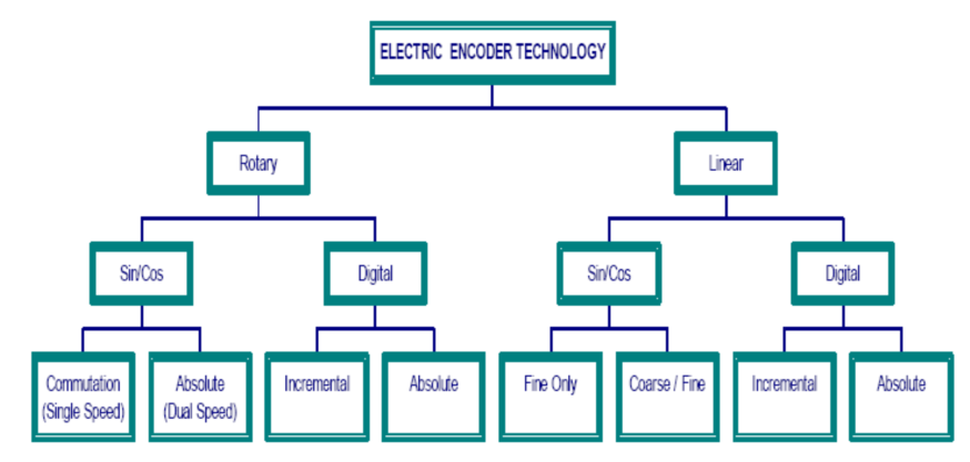
Figure 8 A version of electric position sensor
OstBridge team is a comprehensive solution and components provider of linear encoders, angle encoders, rotary encoders, length gauges, CNC controls, and digital readouts for machines, automation systems, and metrology applications. For Rotary Encoders our product range includes European Brands: HEIDENHAIN, PRECIZIKA, and Chinese Brands: YuHeng. We provide customers with rotary encoders with premium quality, durability, and precision. For the exact application of elevators, machine tools, and servo drives, we can offer customer-specific solutions.